Stepper motors are widely used in precision motion control applications, from 3D printers and CNC machines to robotics and automation systems. A crucial component in ensuring their optimal performance is the stepper motor driver, which controls the motor’s movement by regulating current and step pulses. Understanding how stepper motor drivers work, along with related concepts like stepper motor current, specialized drivers such as the PoStep25-256, and diagnostic tools like a PCB tester, is essential for engineers, hobbyists, and manufacturers.
This article explores these four key topics in depth, providing insights into their functionalities, applications, and importance in modern motion control systems.
Stepper Motor Driver – The Heart of Precision Motion Control
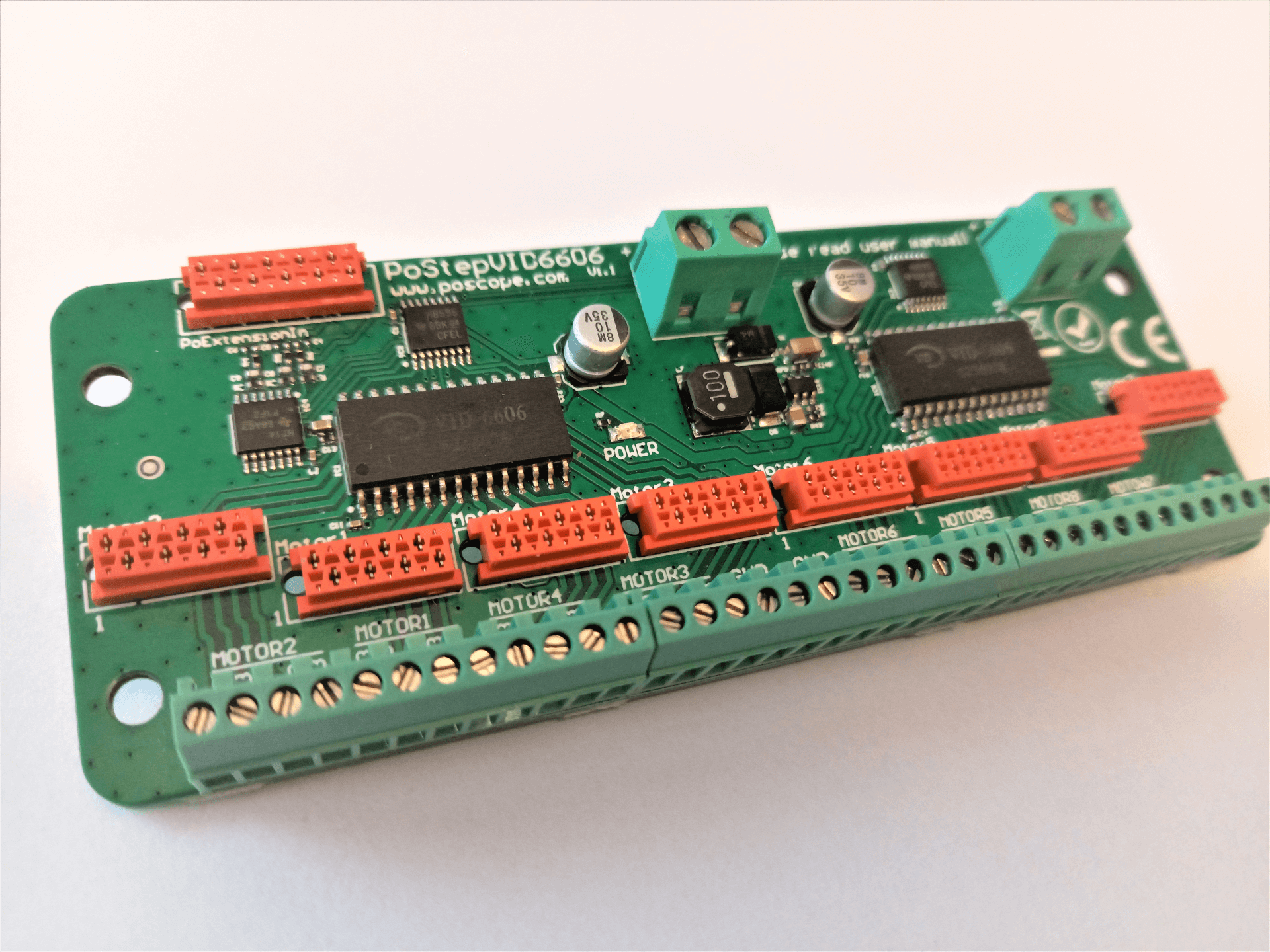
A stepper motor driver is an essential component in motion control systems, acting as the intermediary between a microcontroller (or other control system) and a stepper motor. Unlike standard DC motors, stepper motors move in precise increments, or “steps,” making them ideal for applications requiring accuracy and repeatability. The stepper motor driver plays a critical role in ensuring smooth operation by translating digital signals into mechanical movement while managing power delivery and motor behavior.
How a Stepper Motor Driver Works
The primary function of a stepper motor driver is to regulate the current flowing through the motor’s coils in a controlled sequence. When a microcontroller sends step and direction signals, the driver energizes the motor phases in a specific order, causing the rotor to turn in discrete steps. Advanced stepper motor drivers incorporate microstepping technology, which divides each full step into smaller increments for smoother motion and reduced vibration.
Additionally, the stepper motor driver protects the motor from electrical issues such as overcurrent, overheating, and voltage spikes. Many modern drivers feature adjustable current limits, decay modes (for better braking performance), and diagnostic feedback to optimize performance.
Key Features of a High-Quality Stepper Motor Driver
Current Control – Adjustable current settings ensure compatibility with different motor ratings.
Step Resolution – Support for full-step, half-step, and microstepping (e.g., 1/16 or 1/256 steps).
Protection Mechanisms – Overcurrent, overvoltage, and thermal shutdown safeguards.
Communication Interfaces – Some drivers support UART, SPI, or step/direction inputs for flexible control.
Applications of Stepper Motor Drivers
Stepper motor drivers are used in a wide range of industries, including:
- 3D Printing – Controlling extruders and positioning print heads.
- CNC Machines – Driving axes with high precision.
- Robotics – Enabling accurate joint movements.
- Automated Manufacturing – Feeding systems, conveyor belts, and pick-and-place machines.
Without a properly configured stepper motor driver, a stepper motor would lack the precision and reliability required for these applications. Whether in industrial automation or DIY projects, selecting the right driver is crucial for optimal performance.
Stepper Motor Current – Optimizing Performance and Efficiency
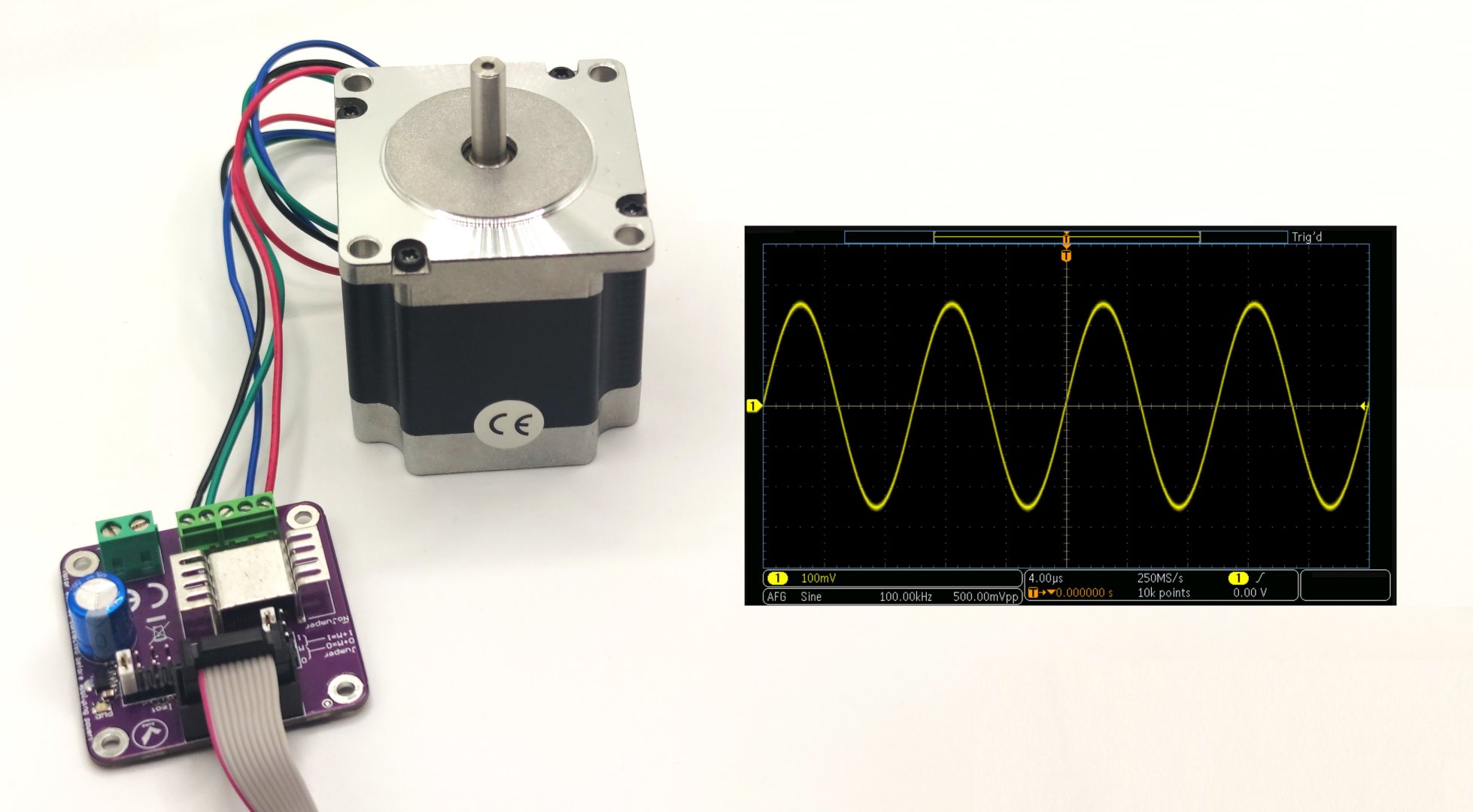
The stepper motor current is one of the most critical parameters in motion control systems, directly affecting torque, heat generation, and overall efficiency. Unlike continuous rotation motors, stepper motors rely on precise current control to maintain position and generate movement. Understanding how to properly set and regulate stepper motor current is essential for maximizing performance while preventing overheating or mechanical failure.
Why Stepper Motor Current Matters
A stepper motor’s torque output is proportional to the stepper motor current flowing through its windings. Too little current results in weak torque and missed steps, while excessive current causes overheating, energy waste, and potential damage to the motor or driver. Most stepper motor drivers allow users to adjust the current limit, ensuring the motor receives just the right amount of power for a given application.
Key Factors Influencing Stepper Motor Current
Motor Specifications – Each stepper motor has a rated current (e.g., 1A, 2A, or higher), which should not be exceeded without proper cooling.
Driver Settings – Adjustable drivers (like the PoStep25-256) let users fine-tune current levels to match motor requirements.
Power Supply Voltage – Higher voltages allow faster current rise in the windings, improving high-speed performance but requiring careful current limiting.
Microstepping Mode – Some microstepping configurations slightly reduce effective current, affecting torque output.
How to Set the Correct Stepper Motor Current
Most modern stepper motor drivers use one of these current adjustment methods:
- Reference Voltage (Vref) – A potentiometer or firmware setting adjusts the current limit based on a reference voltage.
- Digital Configuration – Advanced drivers (such as the PoStep25-256) allow software-based current tuning via UART or SPI.
A general rule is to set the stepper motor current to the motor’s rated value under normal operation. If the motor runs too hot, reducing the current by 10-20% can help, though this may slightly decrease torque.
Consequences of Incorrect Current Settings
- Too Low Current → Weak torque, missed steps, and motor stalling.
- Too High Current → Excessive heat, reduced lifespan, and potential driver failure.
Proper stepper motor current regulation ensures smooth, reliable operation in applications like CNC machines, 3D printers, and robotic arms. The next chapter explores a specialized driver, the PoStep25-256, which offers advanced current control features for demanding applications.
PoStep25-256 – A High-Performance Stepper Motor Driver
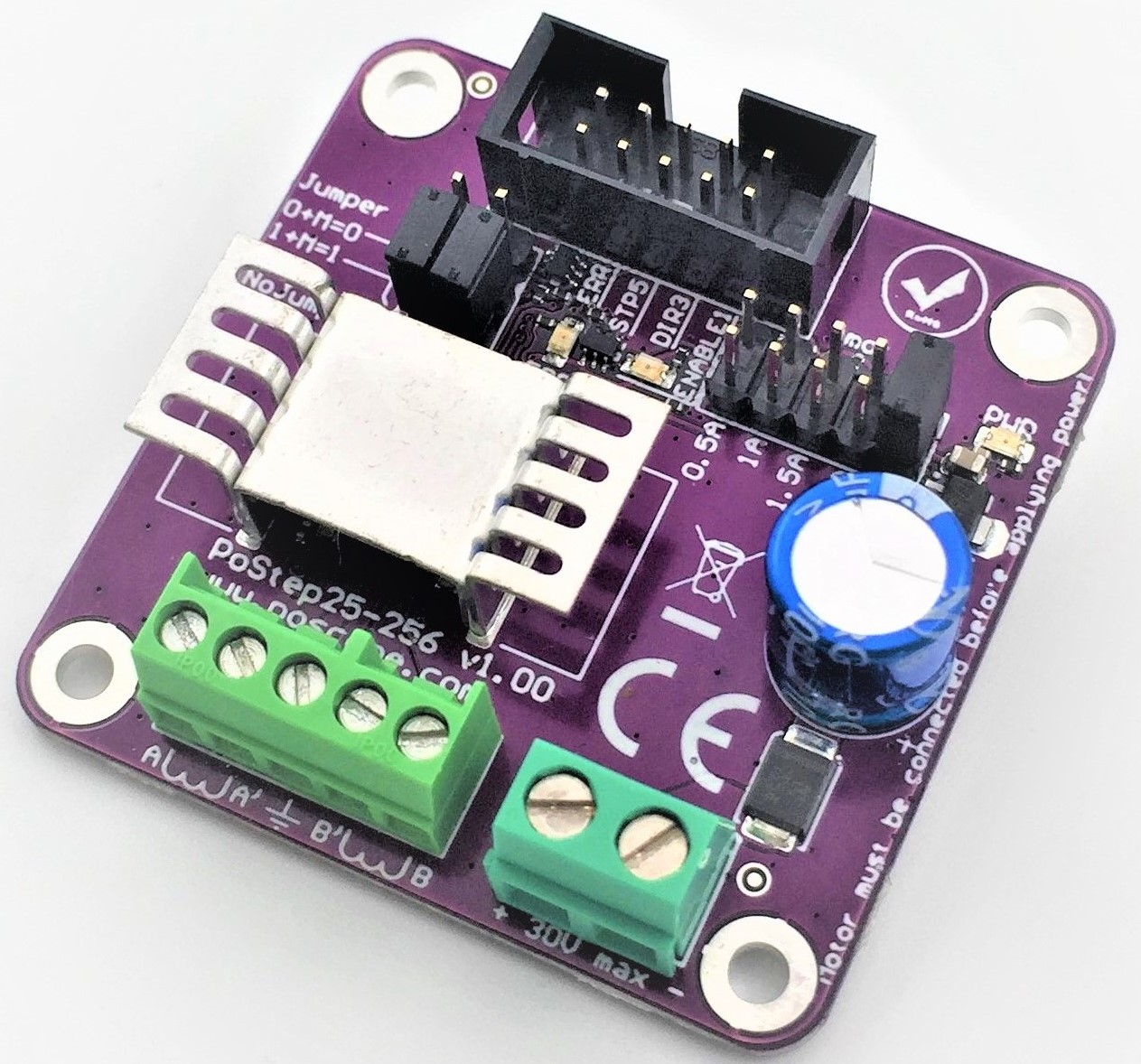
The PoStep25-256 represents a significant advancement in stepper motor control technology, offering engineers and manufacturers unprecedented precision in motion applications. As a sophisticated stepper motor driver, the PoStep25-256 stands out for its ultra-fine microstepping capability, robust power handling, and intelligent current management features. This chapter explores why this driver has become a preferred choice for high-end automation systems and precision machinery.
Technical Specifications and Key Features
The PoStep25-256 distinguishes itself from conventional drivers through several innovative features:
256x Microstepping Resolution – Delivers exceptionally smooth motion by dividing each full step into 256 microsteps, eliminating vibration and noise in sensitive applications.
Advanced Current Control – Automatically adjusts stepper motor current in real-time based on load conditions, optimizing torque while minimizing energy consumption.
Wide Voltage Range – Supports 12-48V DC input, making it versatile for different power systems.
Integrated Protection Circuits – Includes safeguards against overcurrent, overvoltage, and thermal overload.
Multiple Control Interfaces – Compatible with step/direction signals, UART, and SPI for flexible system integration.
Why Choose the PoStep25-256?
For applications demanding the highest precision, the PoStep25-256 offers distinct advantages:
- Medical Equipment – Where silent operation and ultra-smooth motion are critical
- Optical Systems – Requiring vibration-free positioning in microscopy or laser alignment
- High-End 3D Printing – For superior surface finish quality through precise extrusion control
- Laboratory Automation – Where repeatability down to micron-level is essential
The driver’s ability to maintain consistent stepper motor current across all microsteps ensures uniform torque output, a feature that sets it apart from lower-resolution drivers. This makes the PoStep25-256 particularly valuable in applications where traditional drivers might exhibit torque ripple or positional inaccuracies.
Implementation Considerations
While the PoStep25-256 offers superior performance, proper implementation requires attention to:
Heat Management – The driver’s compact design necessitates adequate cooling in high-current applications
Firmware Configuration – Optimal performance requires proper tuning of current limits and microstepping parameters
PCB Layout – Careful board design is needed to minimize electrical noise in sensitive applications
For engineers transitioning from conventional drivers, the PoStep25-256 represents a significant upgrade in motion control capabilities, particularly when paired with a reliable PCB tester for system validation, which we’ll explore in the next chapter.
Read also:
Exploring Key Components in Modern Automation: CNC Pendants, 8 Channel Relay Modules, Automation Control Devices, and Programmable Relays
Reimagining Railroads: The Role of USB I/O Controllers in Streamlining Model Railway Systems
PCB Tester – Ensuring Reliability in Motor Control Systems
A PCB tester is an indispensable tool for validating and troubleshooting the printed circuit boards that form the backbone of stepper motor control systems. Whether you’re manufacturing stepper motor drivers like the PoStep25-256 or integrating them into larger automation setups, a reliable PCB tester helps catch defects early, preventing costly failures in the field. This chapter explores how PCB testers contribute to system reliability and how they’re used in motion control applications.
The Role of PCB Testers in Stepper Motor Systems
Modern stepper motor drivers and their supporting electronics rely on complex PCBs with numerous components. A PCB tester performs several critical functions:
Continuity Testing – Verifies electrical connections between components to detect open or short circuits.
Component Verification – Checks resistors, capacitors, and ICs to ensure they meet specifications.
Signal Integrity Analysis – Tests high-speed digital lines (like step/direction signals) for noise and timing issues.
Power Delivery Validation – Confirms stable voltage and current output from power regulation circuits.
Without thorough testing, issues like poor solder joints, incorrect component placement, or trace damage could lead to erratic motor behavior or even stepper motor driver failure.
Types of PCB Testers for Motor Control Applications
Different PCB tester configurations serve specific needs:
Automated Optical Inspection (AOI) Testers
- Uses cameras to inspect solder joints and component placement.
- Ideal for high-volume production of stepper motor driver boards.
In-Circuit Testers (ICT)
- Probes individual components while powered off.
- Detects wrong resistor values, missing capacitors, or faulty transistors.
Flying Probe Testers
- Contactless testing for prototype or low-volume PCBs.
- Checks connectivity without requiring a custom test fixture.
Functional Testers
- Validates the complete stepper motor driver under real operating conditions.
- Measures stepper motor current output, step accuracy, and thermal performance.
For manufacturers of precision drivers like the PoStep25-256, combining multiple test methods ensures the highest reliability.
PCB Testing in Stepper Motor System Development
A well-designed PCB tester workflow includes:
Pre-Production Testing – Verifies prototype boards before mass production.
In-Line Testing – Screens every PCB during manufacturing.
Final Validation – Confirms that assembled stepper motor drivers meet performance specs.
Common issues detected by PCB testers in motor control systems include:
- Insufficient current-carrying traces → Causes voltage drops and driver overheating.
- Noisy signal paths → Leads to missed steps or erratic motor movement.
- Faulty gate drivers → Results in incorrect stepper motor current regulation.
Integrating PCB Testing into Your Workflow
For engineers and manufacturers:
- For Prototyping – Use flying probe testers to validate designs before committing to production.
- For Mass Production – Implement automated ICT or AOI systems for high-throughput testing.
- For Maintenance – Portable PCB testers help diagnose failed motor controllers in the field.
By incorporating rigorous PCB tester procedures, companies can reduce warranty claims and improve the longevity of stepper motor driver systems.
Integrating Stepper Motor Control for Optimal Performance
The seamless operation of stepper motor systems depends on four critical elements: the stepper motor driver, proper stepper motor current regulation, advanced solutions like the PoStep25-256, and rigorous validation using a PCB tester. Each component plays a vital role in ensuring precision, efficiency, and reliability in motion control applications.
Key Takeaways
Stepper Motor Driver – Acts as the brain of the system, converting control signals into precise mechanical movement. Choosing the right driver ensures smooth operation, microstepping capability, and protection against electrical faults.
Stepper Motor Current – Directly impacts torque, heat dissipation, and efficiency. Proper current adjustment prevents missed steps and overheating while maximizing performance.
PoStep25-256 – Represents the cutting edge in stepper motor control, offering ultra-fine microstepping (256x), adaptive current management, and robust protection features for high-precision applications.
PCB Tester – Essential for validating circuit integrity in motor control systems. From prototyping to mass production, thorough PCB testing prevents failures and ensures long-term reliability.
The Future of Stepper Motor Technology
As automation demands grow, innovations in stepper motor drivers, current regulation, and testing will continue to evolve. Drivers like the PoStep25-256 set new standards for precision, while advanced PCB testers enable faster development cycles and higher-quality manufacturing.
Whether you’re designing CNC machines, 3D printers, or robotic systems, understanding these four pillars—stepper motor driver, stepper motor current, PoStep25-256, and PCB tester—will help you build more efficient, reliable, and high-performing motion control solutions.
By combining the right components with proper tuning and testing, engineers and manufacturers can push the boundaries of precision engineering, delivering systems that meet the ever-increasing demands of modern automation.